

What Is a Vacuum Feeder? A Pneumatic Conveying Device for Bulk Powder Transfer
What Is a Vacuum Feeder?
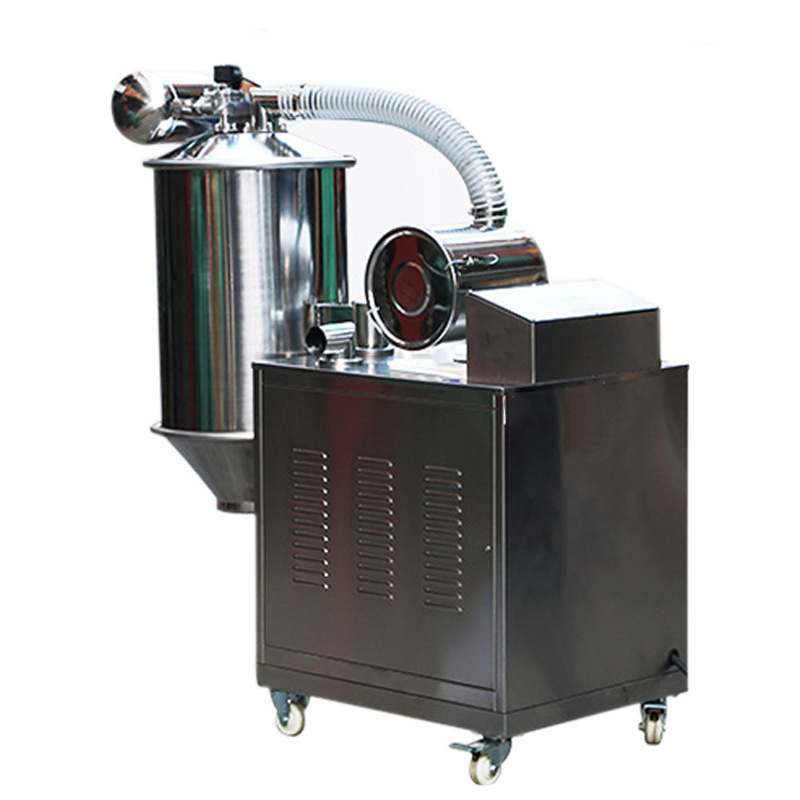
From a practical standpoint, a vacuum feeder is a pneumatic conveying device that uses negative pressure—suction—to pick up bulk powder, granules, or small solid particles from one location and discharge them into another. In powder processing, laboratories, and production environments, it is used to move material through a closed path rather than by manual scooping or open conveying. The purpose is not to grind, mix, or classify the material, but to transfer it cleanly, controllably, and with limited dust release. A vacuum feeder therefore sits between a supply point and a receiving vessel, acting as a link in a larger powder-handling system. It can be configured as a standalone unit or integrated with mixers, mills, screens, dryers, tablet presses, and other process equipment. Its value comes from combining transport with containment: material is drawn into a pickup nozzle, carried through a hose or pipe, separated from the air in a receiver, and released through a discharge valve. For readers comparing equipment, the key point is that a vacuum feeder is a transfer solution, not a particle-size-reduction machine. More details about the TENCAN vacuum feeder are available on the product page.
Core Function and Working Principle
The Basic Transfer Task
A vacuum feeder changes the location and handling state of a material rather than its physical or chemical form. At the start of a cycle, the material may be sitting in a bag, drum, hopper, floor-level bin, or process vessel. At the end, it is expected to arrive in a receiving hopper, reactor, mixer, mill, screen, or packaging line with as little spillage and airborne dust as possible. The input state is therefore a loose bulk solid at one point in the plant; the output state is the same bulk solid delivered to another point under controlled conditions. That distinction matters when specifying a system. A vacuum feeder is not selected primarily for its ability to reduce particle size, blend ingredients, or change temperature. It is selected for reliable pick-up, enclosed transport, and controlled discharge. In a well-designed installation, the feeder becomes part of a repeatable material-flow sequence: connect to the source, draw material into the conveying line, separate it from the transport air, discharge it into the destination, and reset for the next batch or continue in a controlled cycle.
How Negative Pressure Creates Material Flow
The working principle is based on a pressure difference. A vacuum source—typically a vacuum pump, blower, or air-driven ejector, depending on the design—removes air from the receiver vessel. This creates a lower-pressure zone inside the receiver and the connected conveying line. Because the pickup point is at a higher pressure, air rushes toward the receiver, and the moving air stream entrains powder or granules at the pickup nozzle. The mixture of air and material travels through a hose or pipe into the receiver. Inside the receiver, the air slows down and changes direction, allowing the material to fall out of the air stream. A filter or separation element keeps fine particles from being carried toward the vacuum source, while a discharge device releases the collected material into the destination. Many systems work in batches: suction draws material in, the flow is stopped, the receiver is vented or the vacuum is released, and the discharge valve opens. Other systems use sequenced cycles or continuous arrangements. The exact sequence affects throughput, material degradation, and how easily the unit can be integrated with existing process steps.
Process Parameters That Shape Performance
Several parameters determine whether a vacuum feeder performs smoothly or develops problems such as blocked lines, incomplete discharge, or excessive dust. The first is the pickup condition. A pickup nozzle that is too small may restrict flow, while one that is poorly positioned may draw too much air and too little material. The second is air velocity. It must be high enough to keep particles suspended in the line, but unnecessarily high velocity can cause wear, particle breakage, and filter loading. The third is the material itself: bulk density, particle-size distribution, shape, moisture content, cohesiveness, and tendency to generate static charge all influence how easily it can be conveyed. Fine, light powders may remain airborne and challenge the filter; dense or abrasive granules may require more robust lines and slower velocities. Line length, vertical lift, bends, and valve timing also matter. A short, direct run with few bends is easier to convey than a long route with multiple changes in direction. Finally, the discharge sequence must match the receiving process. If the destination cannot accept material continuously, the feeder may need batch timing and level controls rather than a simple on/off command.
Core Components and Key Technologies
Vacuum Source and Air Control
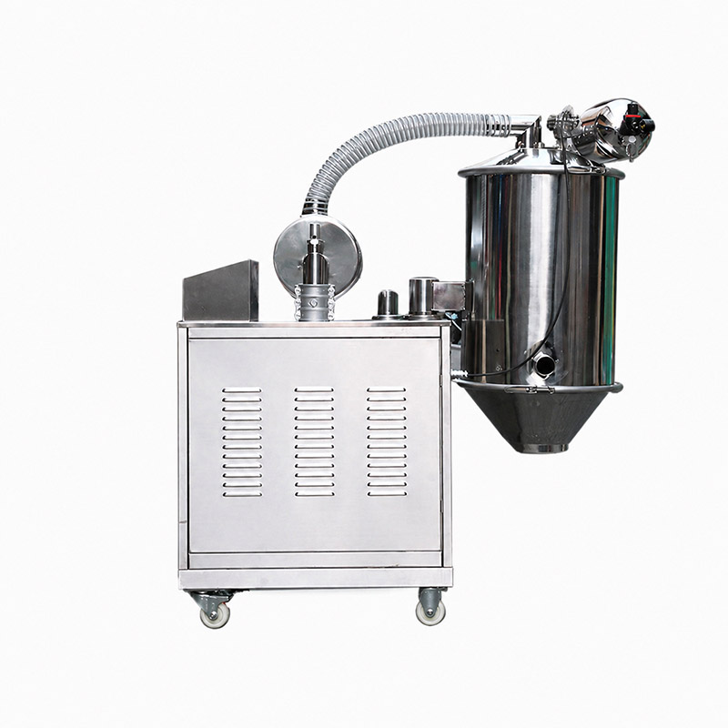
Typical vacuum-feeder designs include a vacuum source, air-control valves, a receiver, a filtration or separation section, a discharge mechanism, and a conveying line with a pickup interface. The vacuum source provides the pressure difference that drives transport. The choice among pump, blower, and ejector styles depends on the required vacuum level, duty cycle, available utilities, and noise or maintenance considerations. Air-control valves determine when suction is applied, when the receiver is vented, and when discharge can occur. The timing of these actions is central to stable operation: if suction remains on while the discharge valve is open, material may not release cleanly; if venting is insufficient, the next cycle may start against residual vacuum. Controls may be simple electromechanical timers or more flexible programmable systems. The important selection question is not simply how much vacuum is available, but whether the air-control sequence can be adjusted to the material and the process. A well-matched sequence reduces blockage risk, improves discharge repeatability, and makes the feeder easier to tune after installation.
Receiver, Filtration, and Discharge
The receiver is the place where transport ends and separation begins. Its volume should be large enough to accept the intended batch without forcing material into the filter, yet not so large that discharge becomes sluggish or cleaning becomes difficult. Inside the receiver, the air–material mixture must decelerate enough for particles to fall toward the outlet. The filter protects the vacuum source and the workplace by capturing fine particles that would otherwise pass through. Filter choice depends on particle size, dust loading, moisture, and cleaning method. A filter that is too coarse may allow fines to carry over; one that is too fine or poorly cleaned may create a pressure drop and reduce conveying performance. Discharge can be achieved with a rotary valve, flap valve, slide gate, or other mechanism, depending on the level of containment and the receiving process. The discharge interface must match the destination: a mixer may need a sealed connection, a drum may need dust-free filling, and a reactor may need inert-gas compatibility. In all cases, the receiver–filter–discharge chain should be evaluated as one system rather than as independent parts.
Conveying Line and Pickup Interface
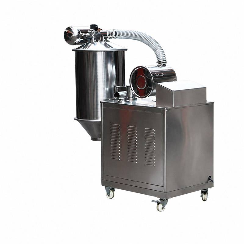
The conveying line links the pickup point to the receiver, and its layout often determines whether a vacuum feeder can be installed without major plant changes. Flexible hoses are useful where the pickup point moves or where equipment must be repositioned, while rigid pipes may be preferred for long runs, high wear resistance, or permanent installations. Bends should be minimized because each bend adds pressure loss and becomes a potential location for material accumulation. The pickup interface is equally important. It may be a wand, lance, hopper, bag-dump connection, or custom adapter designed to draw material from a specific container. The interface should allow material to enter the air stream without creating dead zones, excessive air leakage, or operator exposure to dust. In some applications, a suction wand is moved manually from bag to bag; in others, a fixed pickup is installed under a hopper or at the outlet of a process machine. The right choice depends on how often the source changes, how much operator involvement is acceptable, and how much containment the material requires. These practical details are often more important than a single headline specification.
Key Performance Indicators and Selection Criteria
Throughput and Material Properties
Users often ask for a single throughput figure, but vacuum-feeder capacity is meaningful only when it is tied to the material and the route. Throughput depends on bulk density, particle size, flowability, air velocity, line diameter, distance, lift, and the allowed cycle time. A feeder rated for a free-flowing granule may behave very differently with a cohesive micronized powder or a damp material that tends to bridge. When comparing options, request a rated capacity at a defined bulk density and a defined conveying distance, and ask how the figure was measured. It is also important to distinguish instantaneous transfer rate from average production rate. A system may move material quickly during the suction phase but spend time venting, discharging, and resetting between cycles. For batch processes, the number of cycles per hour and the batch size may matter more than the peak flow rate. For continuous processes, stability over long runs becomes the priority. A realistic selection process matches the feeder to the material's flow behavior, not just to a nominal tonnage or kilogram-per-hour number.
Transfer Distance, Lift, and Layout
Vacuum conveying is sensitive to route geometry. Horizontal distance, vertical lift, the number of bends, and the height of the discharge point all consume pressure differential. A route that looks short on a floor plan may be demanding if it includes several elbows, a long vertical rise, or a flexible hose that collapses under vacuum. Layout also affects maintenance access and cleaning. The receiver needs room for filter service and discharge inspection; the vacuum source needs ventilation and service clearance; the line should be routed to avoid low points where material can settle. If the layout is still being planned, it is better to involve the equipment supplier early than to force a feeder into an unsuitable route. Simple changes—shortening a run, replacing a tight bend, raising a pickup point, or using a larger line—can improve reliability more than increasing vacuum power alone. The best selection is therefore based on a dimensioned layout, not a verbal description such as about ten meters. Use a drawing and state the material, source, destination, and required cycle time.
Containment, Cleaning, and Material Compatibility
For many powder operations, containment is the main reason to choose vacuum transfer. Manual handling can release dust, expose operators, contaminate products, and create cross-contamination between batches. A closed vacuum feeder with properly selected connections and filters can reduce these risks, but containment performance depends on details: gasket quality, valve design, filter integrity, hose connections, and discharge interfaces. Cleaning is closely related. If the same unit handles different products, accessible surfaces, smooth internal geometry, and removable lines may be important. If the material is abrasive, wetted parts should be reviewed for wear. If it is chemically aggressive, elastomers and contact materials must be compatible. If it is sensitive to moisture or oxidation, the ability to use dry air or inert gas may matter. These points should be discussed as process requirements, not as afterthoughts. A feeder that transfers well but is difficult to clean or incompatible with the product will create problems in routine operation. Selection should therefore include a material-contact review, a cleaning review, and a containment review alongside the usual capacity calculation.
Automation, Energy, and Maintenance
Automation can improve repeatability by controlling suction time, venting, discharge, filter cleaning, and interlocks with upstream and downstream equipment. Level sensors in the receiver or destination can prevent overfilling; pressure or vacuum sensors can detect filter blockage or line problems; timers can coordinate batch cycles. The right level of automation depends on the operator model. A laboratory or pilot unit may benefit from simple, transparent controls that are easy to adjust during trials. A production installation may need recipe settings, fault alarms, and integration with a central control system. Energy use should be evaluated over the full cycle rather than by motor rating alone. A system that runs a large vacuum source continuously may be less efficient than one that applies vacuum only when needed, but the duty cycle and process requirements must be considered together. Maintenance is another practical indicator: filter access, valve inspection, hose replacement, and wear-part availability all affect long-term cost. A vacuum feeder is a utility in the process line, so reliability and serviceability are as important as nominal performance.
Applications and Selection Advice
Vacuum feeders are used wherever bulk solids must be moved with limited dust and reasonable layout flexibility. Common settings include chemical and pharmaceutical powder handling, food and nutritional ingredients, battery and ceramic materials, pigments and fillers, plastics and rubber additives, and laboratory or pilot-scale research. They can charge mixers and reactors, feed mills and screens, transfer material from bags or drums, load tablet presses or packaging lines, and connect process steps that are difficult to link with mechanical conveyors. The appropriate choice depends on the user's priorities. A laboratory may value compact size, easy cleaning, and flexible hose routing; a pilot plant may need a balance between flexibility and repeatable controls; a production line may prioritize containment, uptime, and integration with existing automation. Buyers should begin with a clear process description: material name and bulk density, particle-size range, moisture and flow behavior, source and destination, required rate, transfer distance and lift, available utilities, cleaning regime, and containment target. If those details are known, the selection conversation becomes much more productive. For a specific TENCAN configuration, confirm the final selection against the actual material and layout.
Common Questions Before Choosing a Vacuum Feeder
Can a vacuum feeder handle every powder?
No. Vacuum conveying works well for many powders and granules, but very cohesive, wet, sticky, or easily compacted materials may need special pickup, line, or discharge arrangements. Some products are better handled by mechanical conveyors or by a different transfer principle. A material sample and a clear description of its behavior are more useful than a generic category name.
Does the feeder change particle size or blend the product?
Its primary role is transfer. Particles may experience some contact and air shear during conveying, but a vacuum feeder is not a mill, mixer, or classifier. If size reduction or homogenization is required, that should be a separate process step. Gentle conveying may still matter for fragile granules, so air velocity and line geometry should be reviewed.
What information is needed for a reliable quote?
Provide the material, bulk density, particle-size range, temperature, moisture, flow behavior, source and destination, required throughput, transfer distance, vertical lift, available space, utilities, cleaning requirements, and desired level of automation. A dimensioned layout sketch is especially helpful. Without these details, a capacity figure is only a rough indication.
Is a vacuum feeder suitable for clean or sterile areas?
It can be part of a contained transfer strategy, but suitability depends on construction, surface finish, sealing, cleaning access, and filter design. These requirements should be stated explicitly. The same principle applies to explosion hazards, inert-gas blanketing, and cross-contamination control: they require a proper process review rather than a generic add-on.
Where to Learn More
TENCAN's vacuum feeder is listed among the company's research equipment. The product page provides the current product image and contact path for confirming configuration details: Vacuum feeder. Use the page as a starting point, then match the unit to the material, layout, and process requirements described above.
Related Products
Get In Touch
Our professional team will reply to you within one business day. Please feel free to contact us!